(Saturday Social Radio Receiver)
Educational and Fun
February of 2023
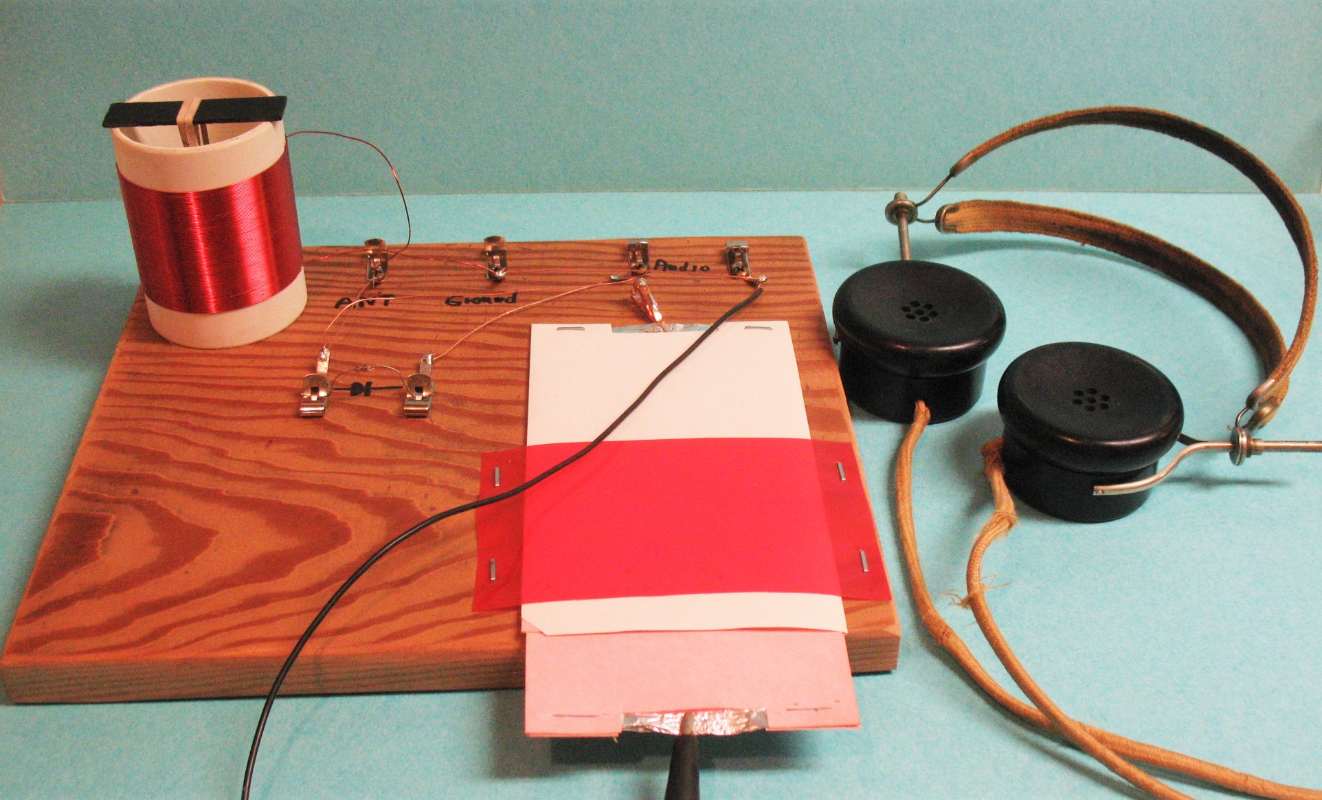
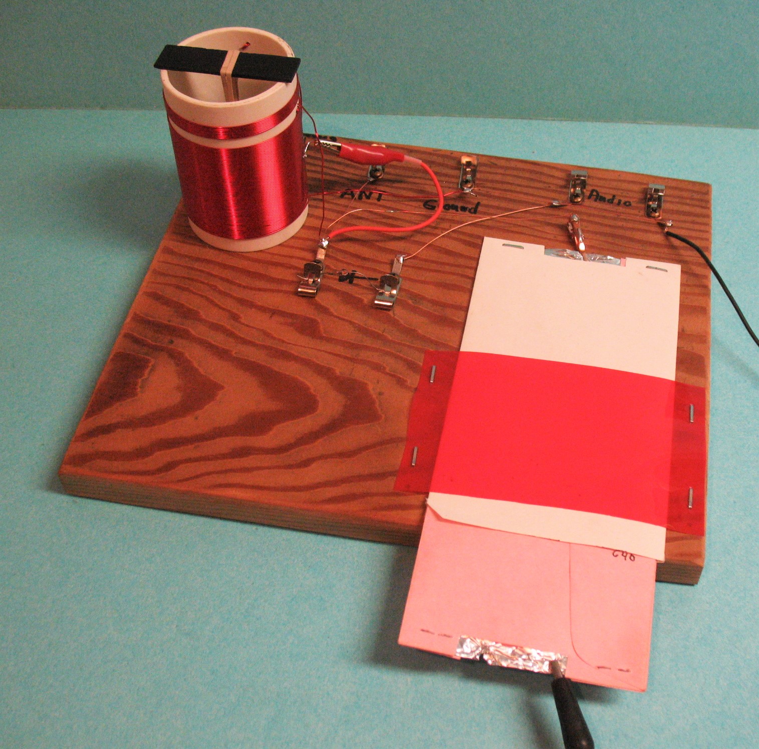
Finished Radio
The Saturday Social Radio (SatSoc) is presented as a platform for
discussion. The key words
and topics in relationship to the SatSoc Radio are: Antenna, Capacitor and Capacitance (pF),
Diode and Detection, Frequency (kHz) and Resonant Frequency, DC Ground and
Radio Frequency Ground, Inductance (L) (uH), Impedance, high Z and low Z,
"Q" efficiency of a coil and others. If you are a seasoned HAM, or a Newbie, this discussion
and build should be fun and educational. If you have not built anything that had
to consider losses and dealing with extremely low energy,
then this will be fun, frustrating and exciting.
I have built radios for over 70 years.
This project was fun, frustrating and very exciting for me to make work.
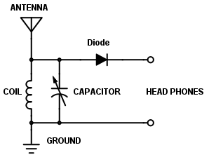
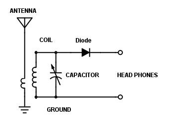
This is a Schematic of a very simple receiver.
It is what we will make and talk about.
If you do not know this schematic, it should be memorized. It is Radio at one of
the simplest forms. As you see none of the components have value labels.
The reason there are no values given is, that this could be a 375 kHz Long Wave Radio
for MCW Beacons or a AM Broadcast Radio, or a 7 MHz Short Wave Am Radio or
a 101 MHz FM Radio (YES).
This simply is a Receiver.
It has many short comings and can be improved with some simple additions.
It is Broad, and not very Selective. We will change things later.
I will talk about the addition at the end.
On the Schematic. Far left top is the Antenna, below that is a coil, below that is
Earth Ground. Across the coil is a Capacitor. On the top is a Detector (Diode).
The Output is fed to High Impedance (Z) Phones or Audio Amplifier.
Simple.
We will make the coil, capacitor and detector. You can use High Z Phones,
Crystal Ear Phone or Audio Amp. We will do some math with the formula
for Inductance, Capacitance and Resonant Frequency.
We will discuss each component of the schematic as it relates to the SatSoc Radio.
The SatSoc Radio is An AM Broadcast Radio.
TOOLS
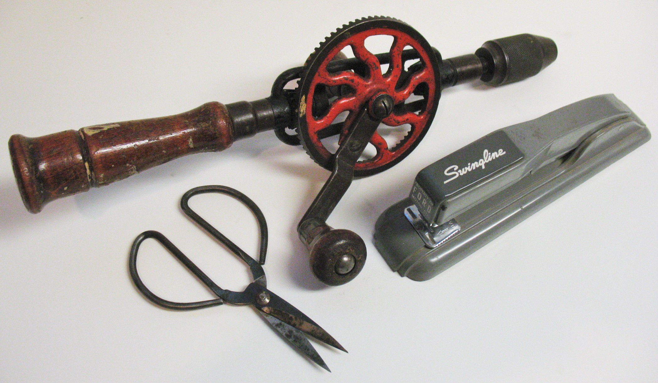
Tools you will need. You can solder some things when we are done testing.
Quick Clips for First Build and Testing
Materials
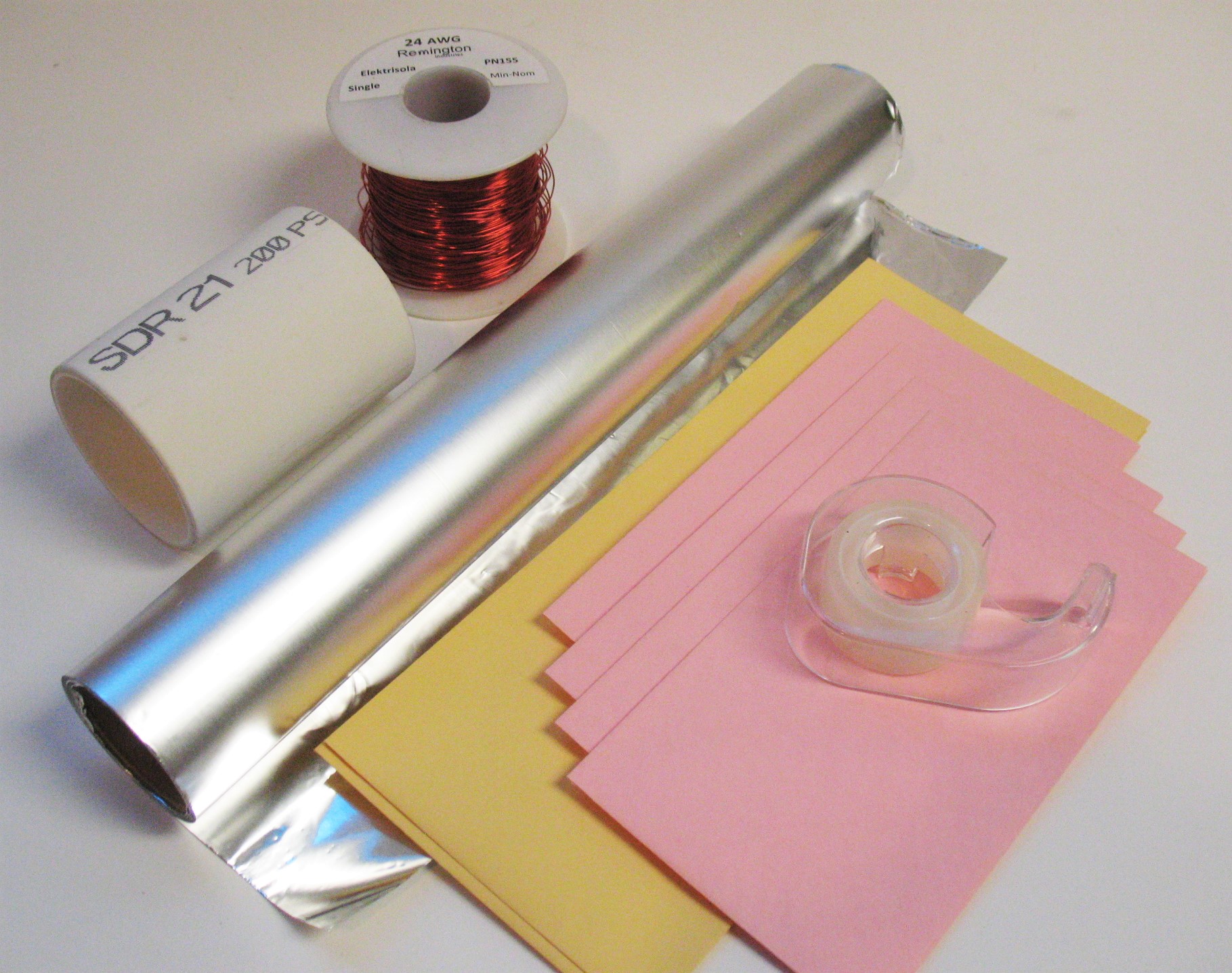
2" PVC Tube 3.5" long or 2" paper Mailing Tube. 22 or 24 Gauge enamel coated magnet
wire. Tin Foil. Envelopes, 4 the same size 3.625 x 6.5, and 1 envelope 4" x 9.5 ". Tape.
The four envelopes must fit inside the other.
Capacitor Materials
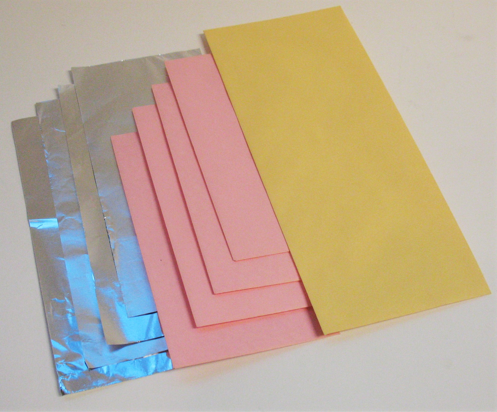
We will make the Variable Capacitor out of Tin Foil and Envelopes.
A Capacitor stores energy in the Electro Static Field. The quantity stored is called Capacitance.
The fundamental unit of Capacitance is the Farad. The letter designation for capacitor is C.
A Farad is to big for radio work. About the size of a 2 pound Coffee Can. This Unit of measure
was named after Michael Faraday. One millionth of a farad is a Microfarad (uf), one millionth of
a microfarad is a Picofarad (pf), we will use Picofarad. Sometimes called a puff. 1 puff, 10 puff etc.
If you have had no experience with this frequency range you could plug numbers for capacitors
and inductors into the Resonant Frequency Formula until you reach what you are looking for.
But first we must have an Idea of what Capacitance we want. That depends on how much
inductance we have. We are building an AM Broadcast Receiver that tunes between
500 kHz to 1600 kHz. We want an Inductor and Capacitor that will have a Resonant Frequency
of between 500 kc and 1600 kc.
We want the radio to be at the high end of the band when the capacitor is close to minimum
and at the bottom of the band when it is close to maximum capacitance. We could have a fixed
capacitor and a variable Inductor to accomplish the same goals, however a variable inductor is
more complicated to build. You can see by our conversation so far there is a relationship between
Inductance and Capacitance for Resonant Frequency. We will go there, but first let us make our
Capacitor. Our Inductor is our 2" form and we will put wire on it to make a coil of around
250 micro henries (uH). You could have found that number by pushing the formula around for
Resonant Frequency, and we will, but we need to start. So I am giving us that number.
Resonant Frequency
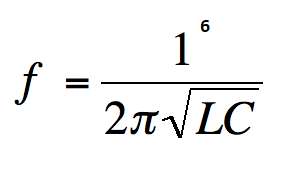
OK, so that reads, Resonant Frequency equals 1 to 6th power divided by 2 Pi
times the square root of the Inductance times the Capacitance.
Where:
Resonant Frequency f in kHz
L = Inductance in uh
C = Capacitance in pf
2PI = 6.283
We use Resonant Frequency to find value of our home made capacitor by guessing at the value.
We want a Resonant Frequency close to 500 kHz.
You can use calculator, spread sheet or basic program or what ever you know how to write.
So if we try 100 pf and 250 uh we get 1006.58 kc
So if we try 200 pf and 250 uh we get 711.76 kc
So if we try 300 pf and 250 uh we get 581.15 kc
So if we try 400 pf and 250 uh we get 503.29 kc
Note: 100 pf with 100 uh = 1591 kHz
Now we know that we want a capacitor with a value of 400pf.
How do we make a capacitor. We will use tin foil for plates and paper for a dielectric.
The Dielectric is what is between the plates of the capacitor. It could be air, acetate,
paper or glass to name a few. The distance between the plates and the area of the plates
and the dielectric constant determine the value of the capacitor.
A good Chart for Dielectric Constants is in the ARRL Hand Book
Dielectric value of Air is 1 and Paper is 3.
Capacitor Formula
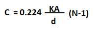
Where:
C is Capacitance in pf
K is the Dielectric Constant
A is The Area of one side of one plate in square inches
d is the distance between Plates in inches
N is the Number of Plates
So that formula reads:
Capacitance equals .224 times the dielectric constant times the area
divided by the separation times number of plates minus 1.
Our envelopes are 3.625 x 6.5 our tin foil will be a bit smaller 3.5 x 6.375.
That is an Area of 22.312
Our Dielectric Constant is 3
The distance between the Plates is .010 (in the real world a lot bigger)
The Number of Plates is 4
We run the formula:
The Formula gives us 3009.44 pf only true if you put a book on top of it.
In the real world for our Envelope Capacitor it is about 455 pf.
Now we can Make our Capacitor.
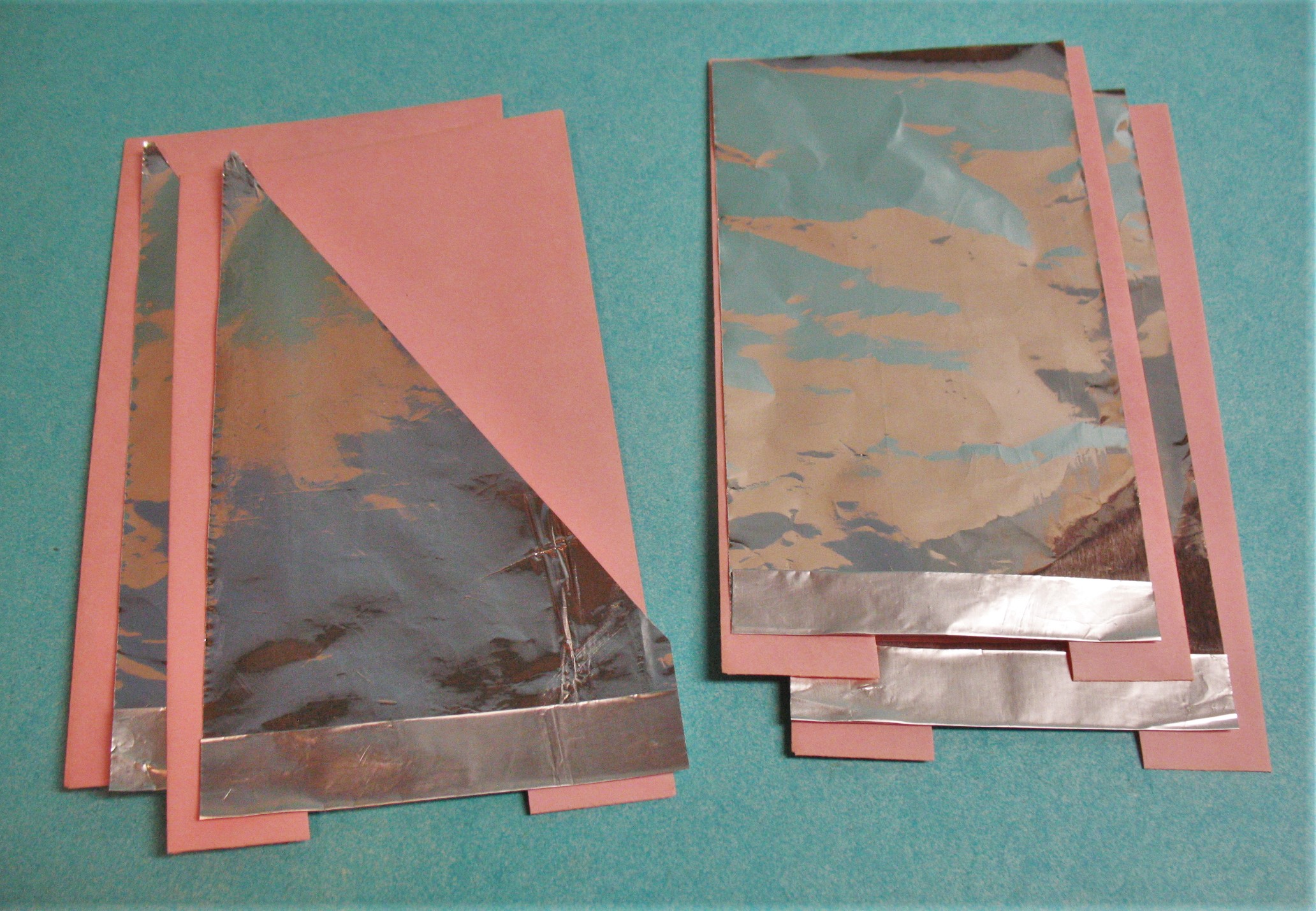
The first thing to do is cut the tin foil in 4 strips 3.5" x 7.5". The extra length is to fold .5"
twice to make it thicker at one end. Cut a Slot in the ends of all of the envelopes.
Fold the tin foil 1/2" over on the ends twice it should fit now, if not trim to fit. Stuff two
smaller envelopes and lick shut. Take these two of the smaller ones and staple the ends
as in the photo, this is the stator (stationary part). Take the Long envelope and trim
it to be 6.750 long. Put the stator with tin foil Notch first into the
Out Side envelope and staple as in the photo. Now fold the Rotor Tin Foil
1/2 " over on the end. Now cut from the folded corner to the top
opposite side with scissors. Place tin foil into envelopes, folds into the notch.
Now take rotor envelopes and look through at the light and turn so both facing same way.
Now staple outside ends together. Insert the Rotor into the Stator
one envelope on top and one in the middle envelope of the Stator.
.
You NOW have a Variable Capacitor. You will be able to mark the Rotor
with lines for Stations, Frequency or Capacitance
By pulling out, or pushing in we change the capacitance.
Mark the Inside envelope so as not to
pull it out to far. About 1/2 inch from the end.
A Note about Coil and Cap, L and C with fixed Frequency. The ratio of L and C can be varied,
small C and large L or large C and small L for same frequency. But the Reactance Changes.
Resistance and Reactance combine for Impedance. The subtleties of this topic are too
complex for this project.
Now For Our Coil
Coil Form and Wire
When we wrap a coil we make an Inductor. The designator letter for
Inductance is L.The Inductor stores energy in the Electro Magnetic Field.
The unit of Inductance is Henry. For most of radio spectrum,
we use Microhenry uh.
The coil forms can be 2" PVC or 2" Paper mailing tube. The diameter
of 2" PVC is 2.375. The diameter of Paper Mailing Tube is 2.125.
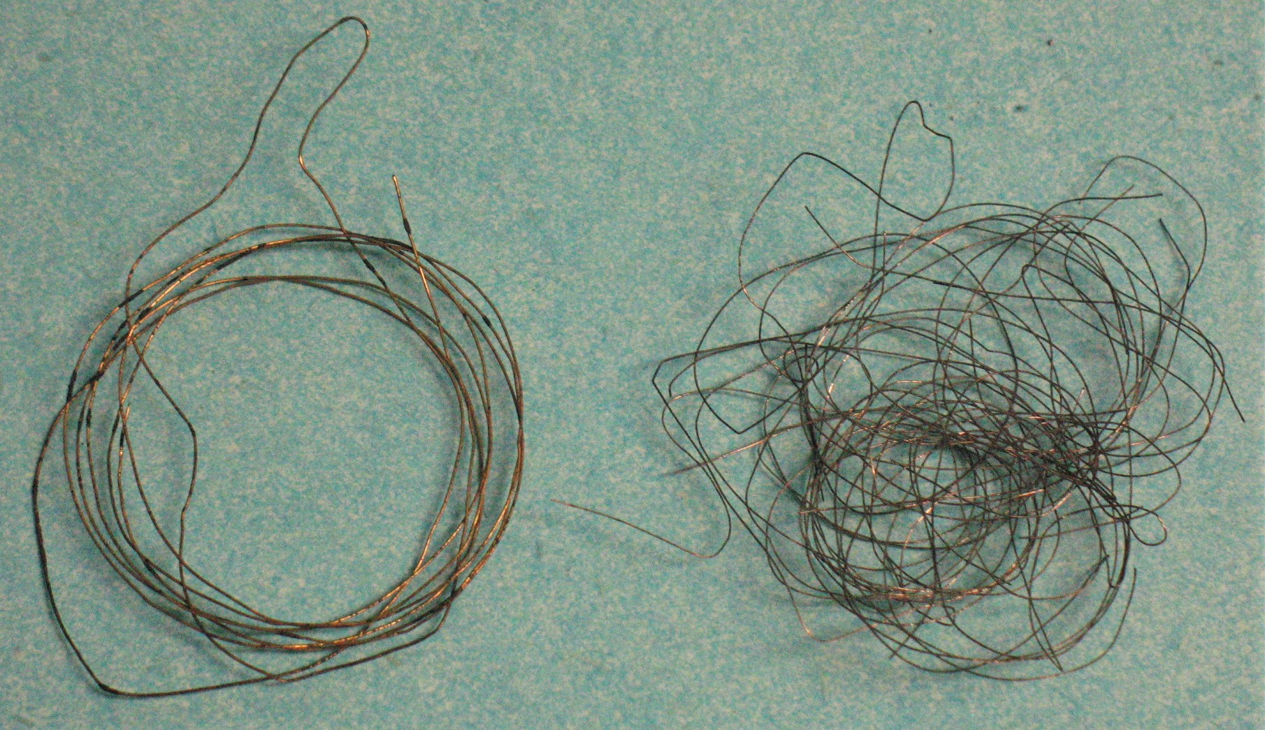
The Wire size could be 22 or 24 Gauge Wire.
That said, you can use any practical size form and reasonable size wire,
However the choices made here determine the performance of the radio.
The paper tube is a better choice for Q (efficiency) of the coil. It is harder to work with,
softer, bends and will not hold up like the PVC. The PVC is what I would recommend.
Stronger and drills better, you will be able to pull on the wire harder to get a tight coil.
The PVC is not far from Paper as far as Q.
Cut your tube to 3" long. Drill two holes on each end, staggered a bit as in the photo.
The holes separation depends on the diameter of the form and what Gauge wire we use.
I gave you 250 microhenries (uH).
You could go back and run the resonant frequency formula knowing you have a 455pf capacitor.
You will find that a coil with 230 uh and 455pf your Resonant Frequency will be 491 kHz.
So how do we know where to drill the holes in the coil form? We have to wrap a certain
number of turns of wire on our form to achieve 250uh inductance. The wire has a
thickness and if we multiply the diameter by the number of turns we will
have the length of the coil.
So Wire Gauge, Diameter of the Form, Coil winding Length tell us what the
inductance will be.
The formula for Inductance of a known coil is:
Where:
L = inductance in uh
a = Coil radius in inches
b = Coil length in inches
n = number of turns
The formula reads:
Inductance equals a squared times n squared divided by 9a + 10b.
So what wire are you going to use? What form are you going to use?
I am going to use 2" pvc, its Diameter is 2.375
I am using 22 Gauge. It has a diameter of .027.
I know I want an answer of 250 uh for L.
I know radius a = 1.1875
I do not know the length so lets guess 1". How many turns of wire can go into 1".
37 turns.
I run the formula. I get 93uh, I need more turns. Lets try 60 turns. I get 188uh.
Let us try 70 turns. I get 233 uh.
Let us try 74 turns. I get 251 uh of Inductance.
This Coil should have a Q of about 1213.
Do not forget to change the coil length every time you change the turns count.
22 Gauge diameter is .027
24 Gauge diameter is .020
Coil for Paper Form. Cut tube to 3.5"
24 Gauge, 75 turns, Coil length 1.5", 258uh
22 Gauge, 84 turns, Coil length 2.2", 252uh
Coil for PVC Form.
24 Gauge, 65 turns, Coil length 1.3", 251uh
22 Gauge, 75turns, Coil length 2", 258uh
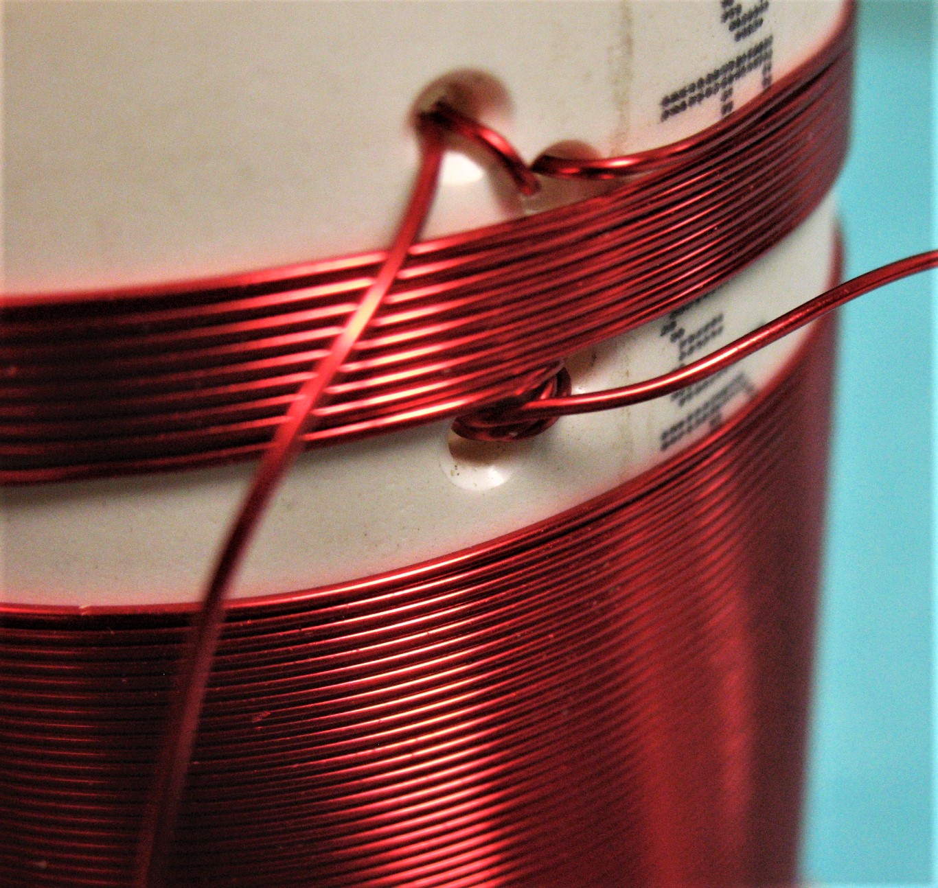
How I wrap a coil is pretty simple. I take the end of the wire on the spool and I put it
into the holes on the form. I pass it through the holes twice and leave it on the inside,
having 5 or 6 " tucked inside. Set the coil form down and spool off wire as you walk to
other side of the room and wrap the wire around something to hold it . Then I take a rag
and pull the wire through the rag going back to the coil form. That takes kinks out of the
wire. I start with the wire on top. I roll the form toward myself
keeping tension on the wire.
Now We have a Coil and Variable Capacitor.
Detectors - Rectification
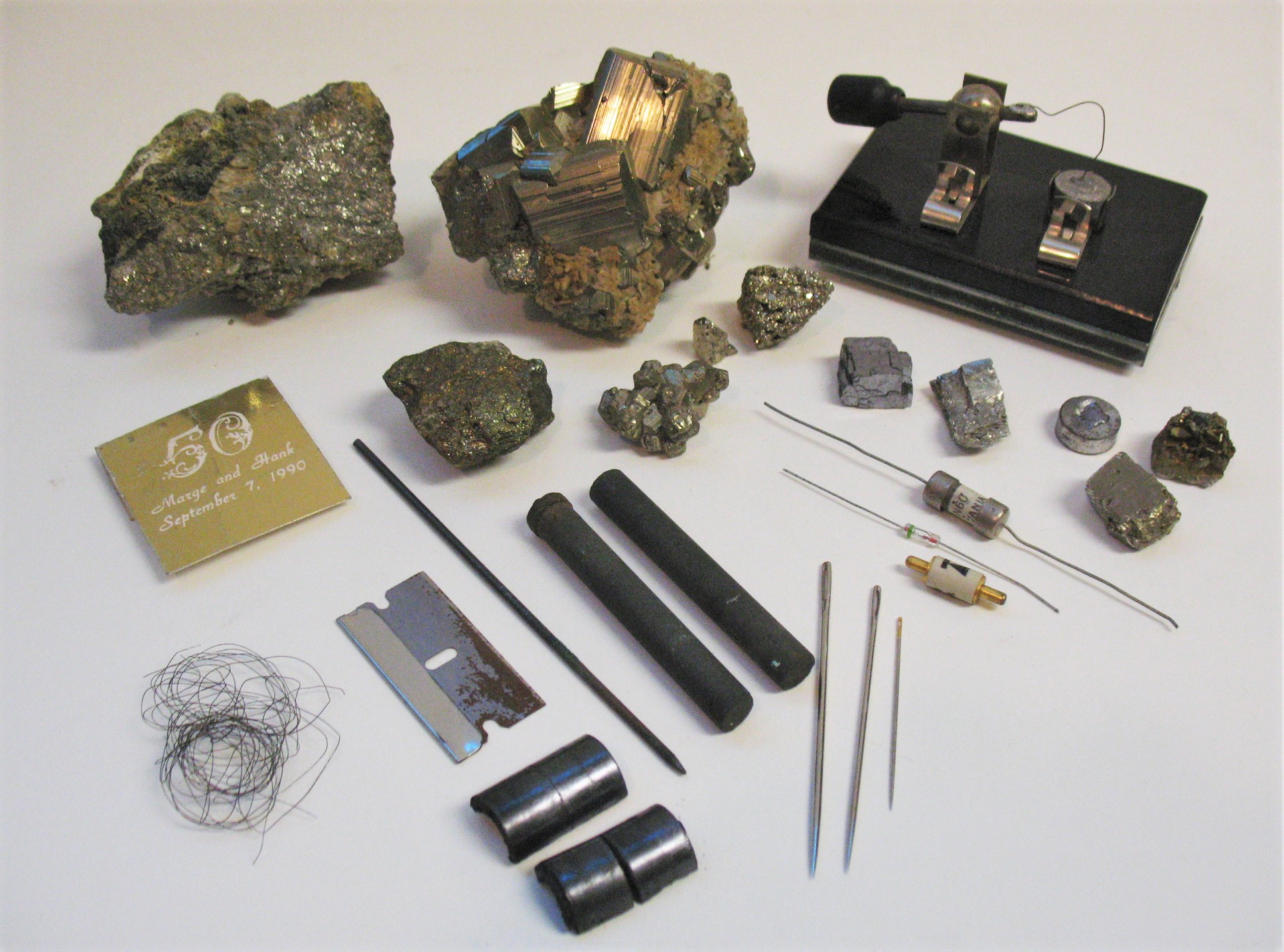
These are some things that can rectify an Amplitude Modulated Signal. Diodes 1N34A,
1N60, Galina, Iron Pyrite, Carbon Rods and Needle, Razor Blade and Graphite,
and many more.
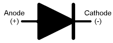
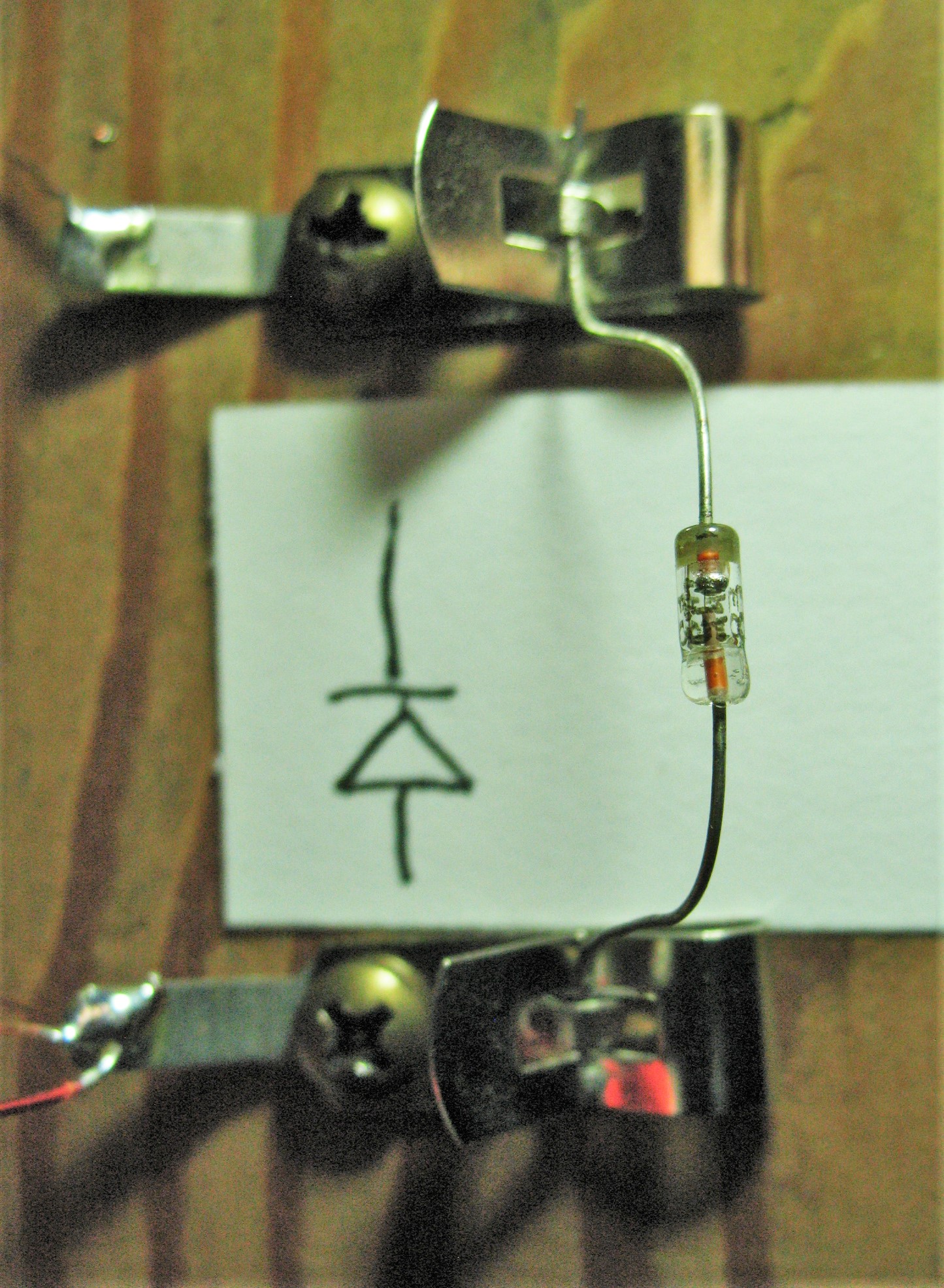
This is the symbol for Diode. The Letter is D.
These diodes are point contact diodes.
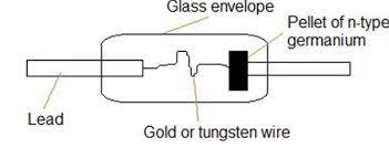
Looks like the Black Crystal Stand.
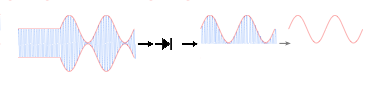
A graphic of the envelope of an AM modulated RF transmission.
Far left is Carrier Wave, Then 100% modulation, Then rectification,
Then half wave with carrier, Then Voltage Curve.
For the Satsoc Radio the best component for this job is a Diode.
If you buy ten 1N34A Diodes, and you put them in the radio one at a time with
the radio tuned to the local station, one or more will be better than the others.
If you repeat that test on a weak station one or more will be better than the rest.
Not necessarily the best from the previous test. Some will pass more voltage
some will be more sensitive. Now that I said Diode is best for the Satsoc Radio,
You should have one for testing. But we will make our own detectors.
Investigation into crystal detectors has been going on for over 100 years. Still is.
There are more than 25 crystals found in nature that can act as a Diode.
With todays AI and Institutional and Industrial research, new ones come
regularly that have been man made.
There is a form of Detection that is called "Imperfect Contact Detection".
Another form of detection is by "Dissimilar Materials."
I will not explain how these work, because I do not know.
They work, it is magic, it is fun.
We will need a source of Carbon, if you have carbon bars Great!
For those who do not we will find them.
A Double A battery 1.5 volts Alkaline has a carbon shell.
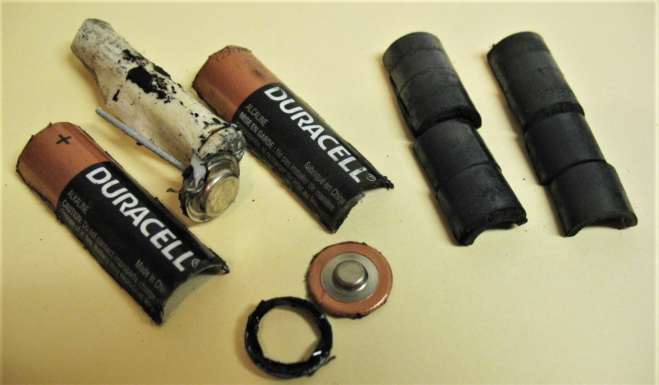
If you take a AA Alkaline Battery apart with a Dremel abrasive wheel, this is what
you get. Around the ends first. Then slit the sides. The carbon is an outer assembly
of 8 half rounds put inside the battery tube, as seen here.
We will use these with a sewing Needle.
Now that we have a Coil, a Capacitor and an Detector we need Audio.
Audio
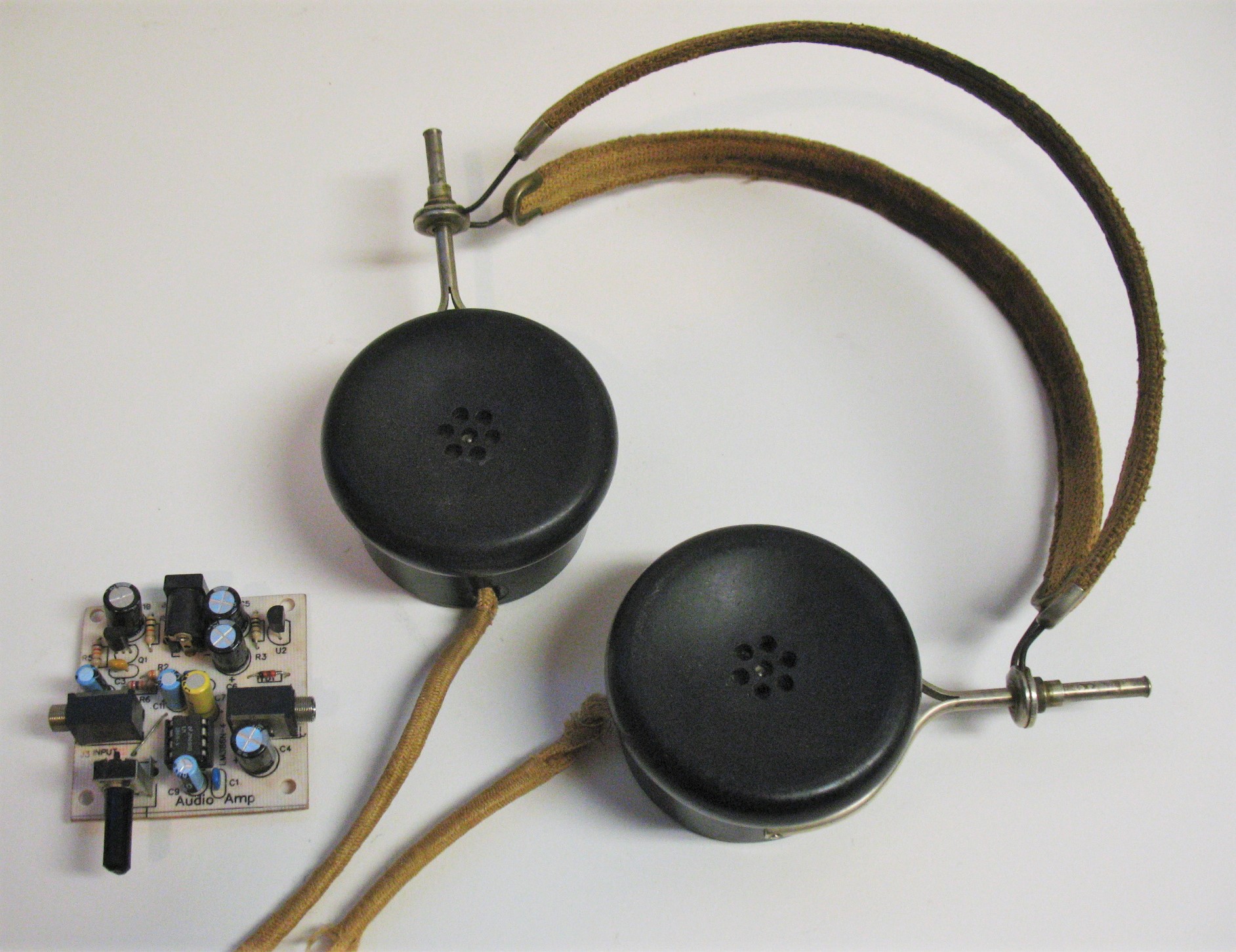
Audio Amp and High Impedance Headphones
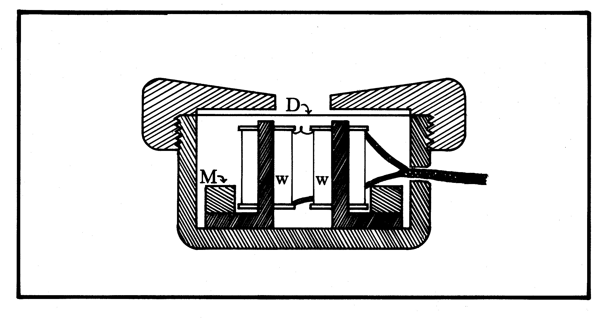
Inside High Impedance Head Phone
The output of the SatSoc Radio wants a Hi Impedance Load.
Z is the letter for Impedance. Impedance is the opposition to AC.
Today most Speakers and Headphones are in the 3 to 8 ohm range for DC resistance
and a rule of thumb of about 40 ohms Z impedance. Our Radio needs Hi Z .
2000 to 10,000 ohms DC resistance, and having 10K Z to 50K Z Impedance.
The Headphones Pictured here (have a Z of 10K), they have magnets and
electro magnets and a steel diaphram. So the diaphram is under some stress
by the permanent magnet. When the audio voltage, changing in proportion
to the audio presented at the transmitting station, it is applied to the windings
of the electromagnet, then the diaphram vibrates at that audio frequency.
If you have never heard a radio of this design then you are in for a pleasant
surprise. The audio is pure with no distortion. Without amplification
there is no distortion. You can use an audio amp,
Computer Audio amp or whatever you have.
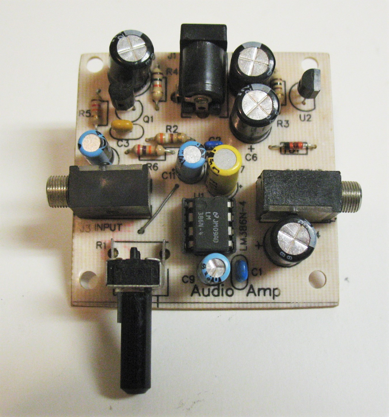
I use this a lot, Home Brew LM386
Antenna and Ground Systems
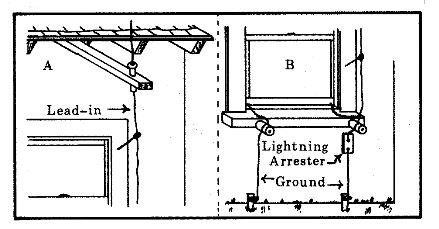
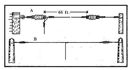
My drawings from 1971.
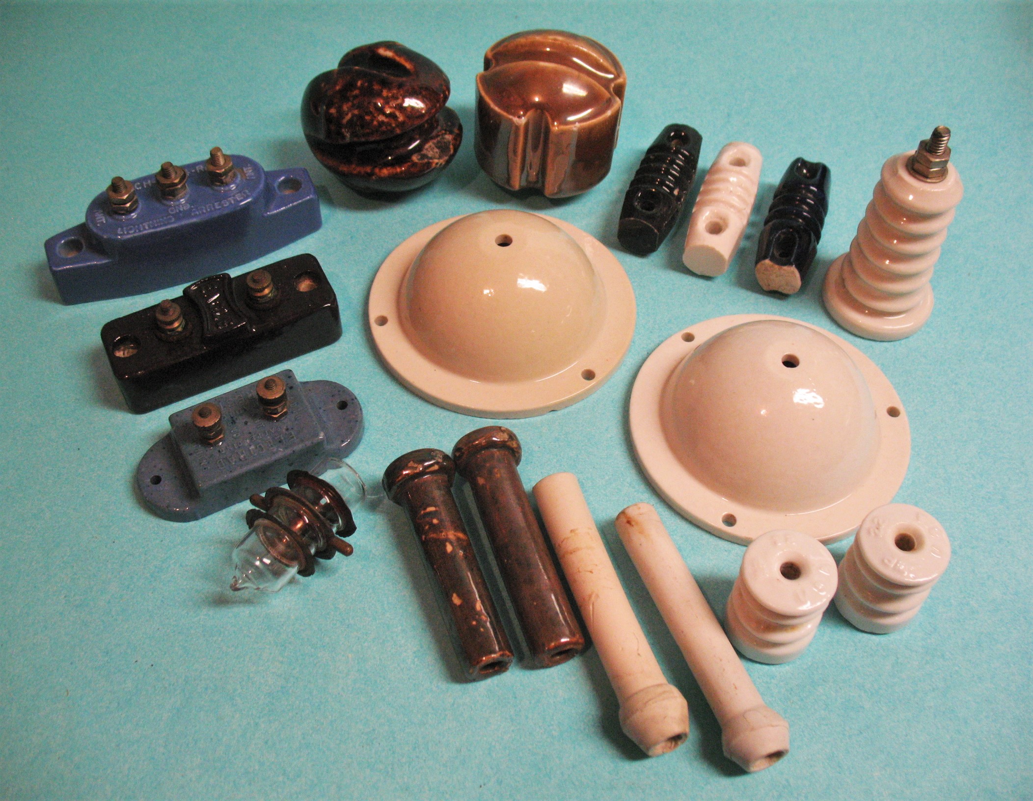
Here are Insulators and Lightening Arrestors.
The big Round Ones are Pass Through insulators, one inside the house the other outside.
The two brown ones at the back are Egg Strain insulators, and more strain insulators
black, white and blue to the right. Standing tall is a Stand Off insulator. To the left
are Lightning Arrestors, blue, black, blue and a vacuum arrestor. At the bottom are
knob and tubes from the Early House Wiring Days, we can use these as well.
Glass and Ceramic are best but any insulating material works. Ceramic should be
glazed or boiled in wax. Dry wood was used after boiling in wax. Find Ceramic
or Glass if you can.
In this kind of radio receiver there is no room for "that will be OK". No part of the
Antenna, Ground Coil, Capacitor, Detector, and Headphones is any less important.
We are trying to use the energy of the transmitting station to power our Radio.
If we manage to gather all the energy we can at the antenna and squander it with a
bad Coil or Ground we lose. If we throw it away with a bad Detector, we lose. If our
head phones have a bad cord or are damaged, we lose. The antenna needs to be as
high and as long as possible.( I understand you have to use what you have, But I want you
to know how it should be) The antenna can not touch anything except an Insulator.
The ground needs to be short as possible. Clean and tight.
What would pass for a DC might not be good enough for our weak RF energy. If you live
near town you should have enough power to drive a RED LED with the signal.
If you live out you will have enough for the radio. Day time signal from our local station is
5,000 watts, at sun down it goes to 500 watts. I still hear it well at nights 9 miles away.
Your Beam or your 2m Vertical will not do. You need 50 ft of wire or more as high
as you can go and as long as it can be.
The antenna is your power source.
Now let us build this radio and see what it Can Do!
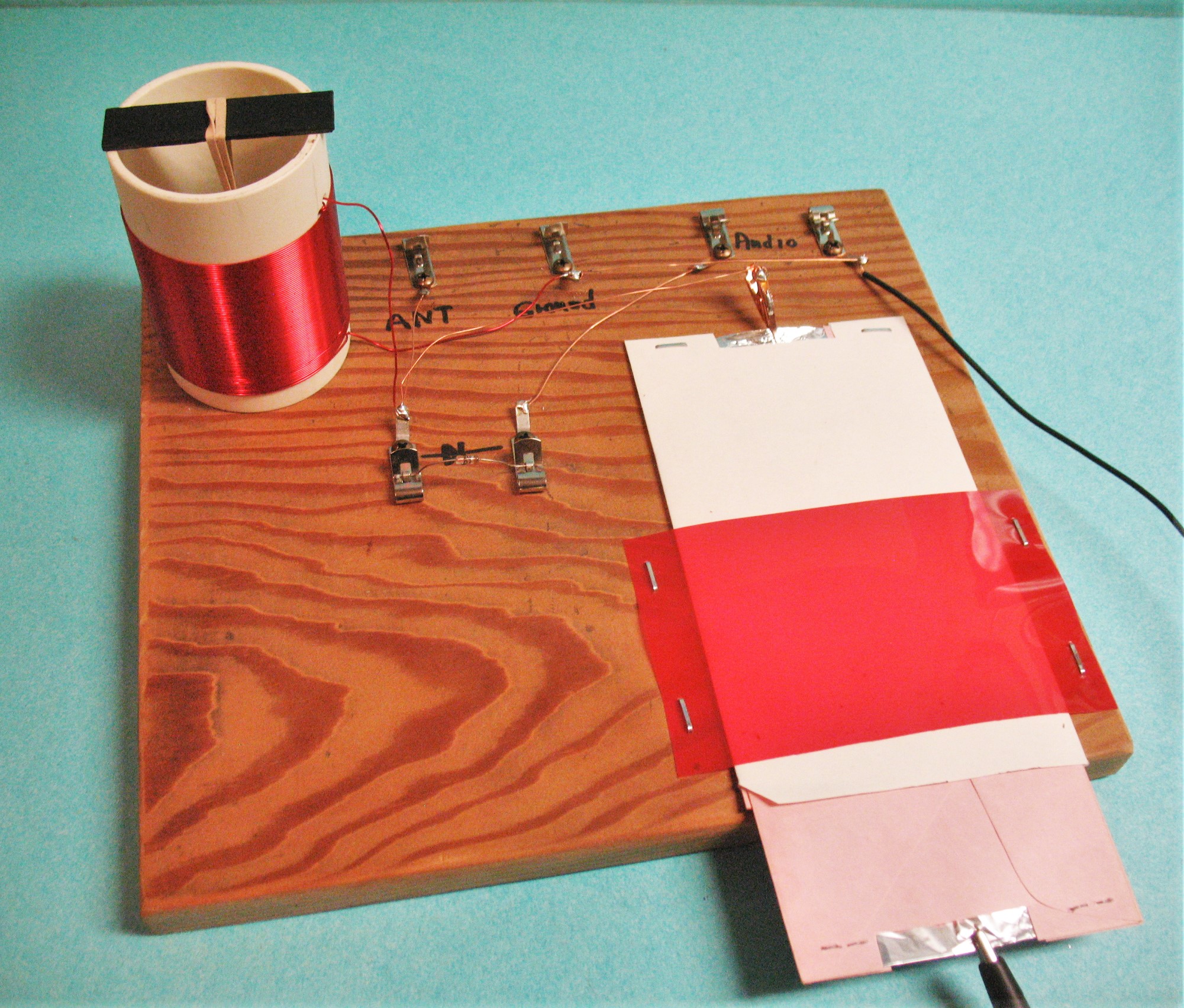
This is what I made.
You can use quick clips or solder. I will use Soldering Lugs and Solder and Fahnstock clips.
. We need quick clips for testing detectors. The capacitor has two quick clips.
The capacitor's tin foil is fragile so pull and push on the envelopes to Open and Close the
capacitor, not the quick clip.
Look back to the schematic and hook it together with a good diode to start.
I used a board to hold things down, with a spot for adding detectors to test. I stapled
the capacitor at the back and made a strap for the front
.
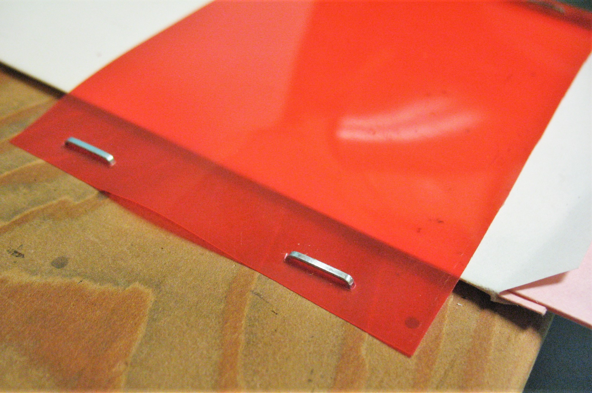
Made from plastic binder separator.
Stator Clipped at the Back.
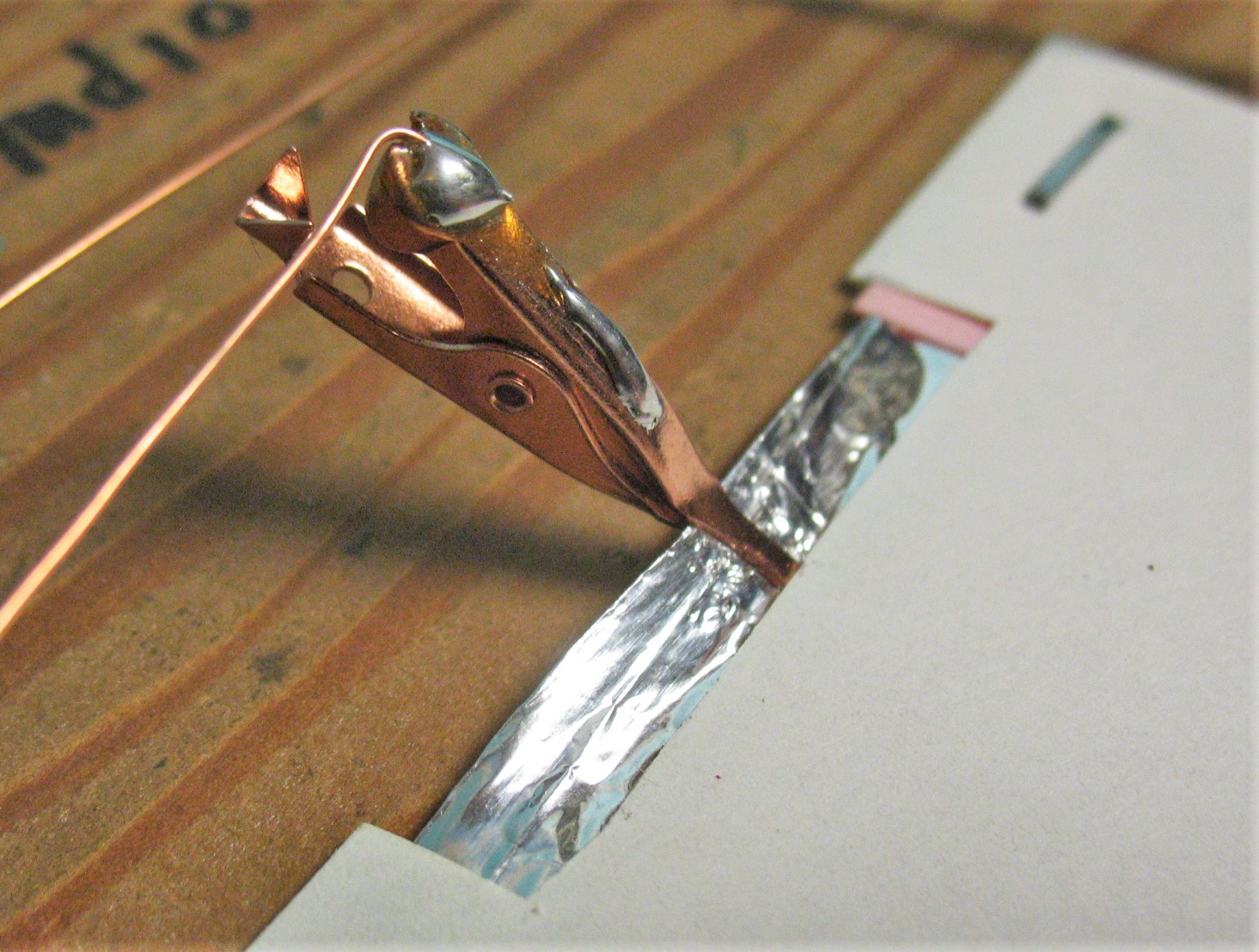
Detector Holder Close Up (paper for clarity)
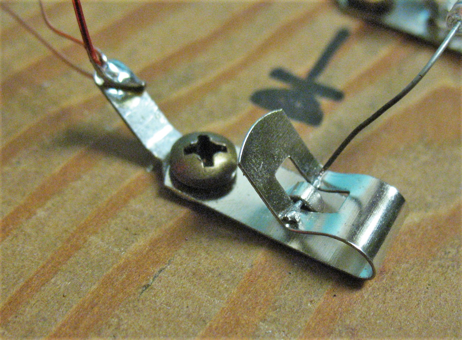
Screw, Fahnstock and Solder Lug.
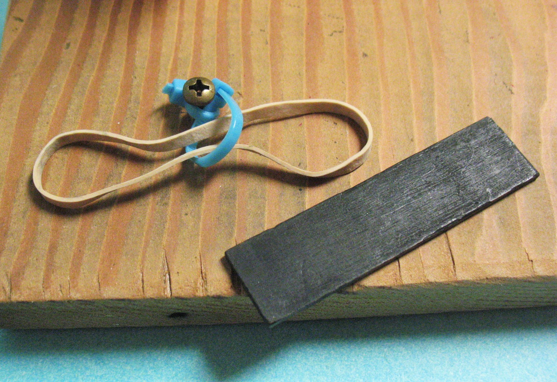
Coil Hold Down with Screw, Zip Ties, Stick and Rubber Band
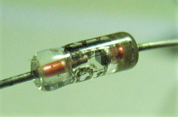
I shot this close up of our Point Contact Diode. See How it looks like
the Knock Down Crystal Stand Below.
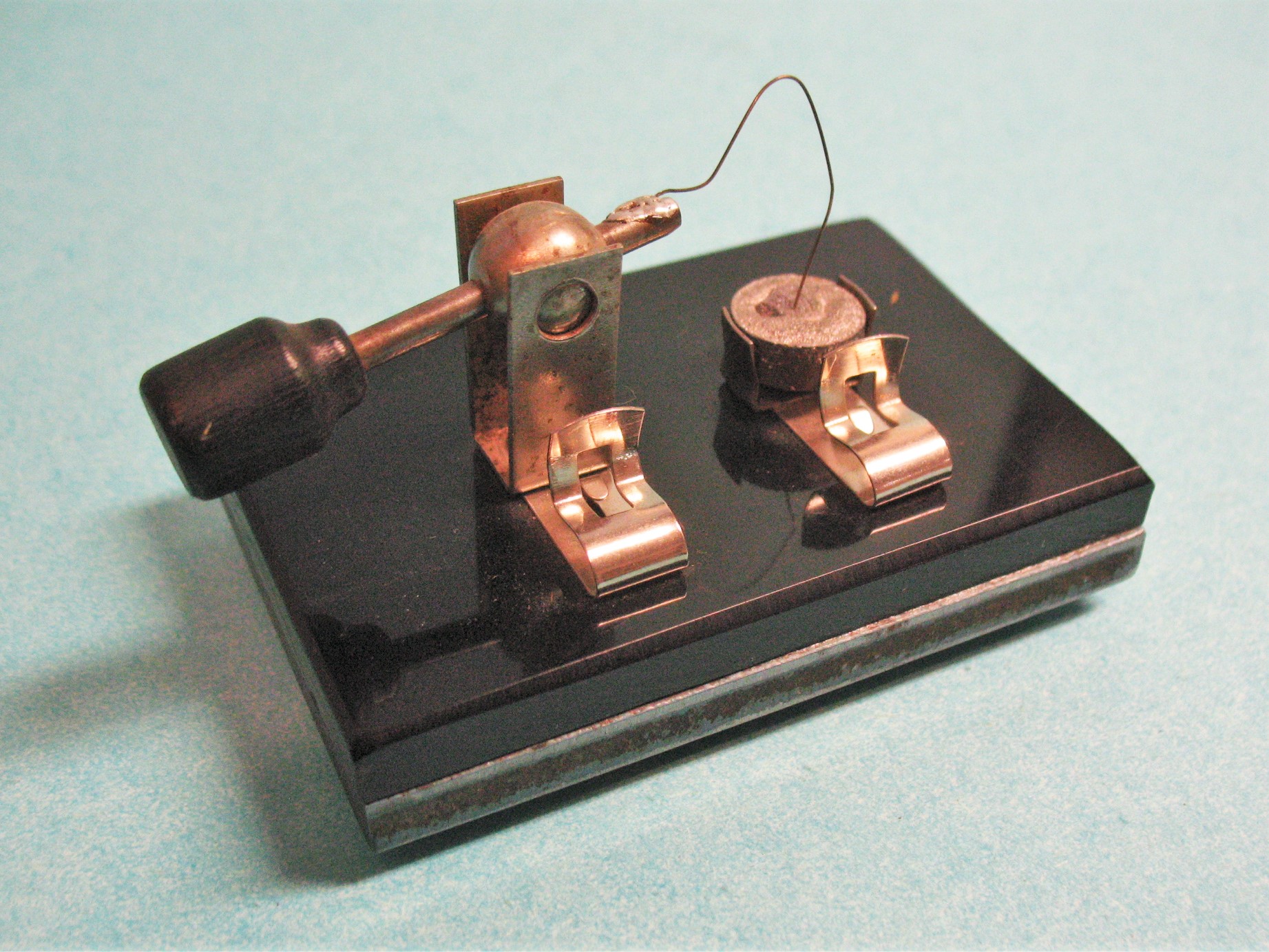
I made this out of Black Plastic and 1/4 inch steel plate for weight.
See the Cat's Whisker touching the crystal in both pictures, The chunk of
crystal is the Cathode and the Cat's Whisker is the Anode. The Cat's
Whisker is Phosphorus Bronze and must be cut square with scissors only.
The Crystal here is Lead Sulfide Ore, (Galena) and it is embedded in Wood's
Metal ( 50% Bismuth, 26.7% Lead, 13.3 % Tin and 10% Cadmium)
Melts at 158 º F. High temp would damage crystal.
Testing
First Testing Daytime.
Now that we have a radio we can do some testing and have some fun.
First we need to hook up the Diode IN34A to start. As you saw the
Diode can come in a glass package. If you have electronic junk you
are throwing out you might look for diodes. You might be surprised
at how many you find.
Attach the antenna and ground. Put your head phones on or turn on
your amplifier. Slide your Capacitor in and out until you get a station
at its loudest, you can put a pencil mark on the rotor to mark that station.
Slide in and out, look for more. Turn the volume up on the amplifier
and look again. You should have two or three marked.
Tune to the strongest station.
FYI
At Night time, the local
Stations Reduce Power to protect the Clear Channel Stations. At night
time you will hear stations a 1000 miles away or more. You will hear
several stations, with no trouble. You will hear classic examples QSB
in the form of fading and flutter.
Testing
Remove the diode.
Now take the carbon from the alkaline battery, and clip it in place of the
Diode. Place the sewing needle across the two carbon halves.
Nudge the needle, you should hear popping or scratching. Keep
nudging until the radio signal appears. This is imperfect contact and/or
dissimilar materials detection.
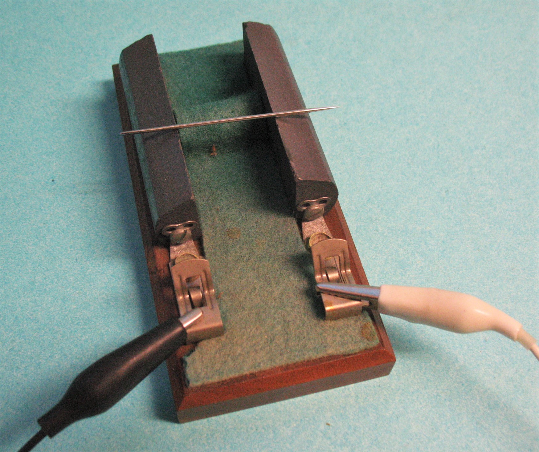
I made this Carbon Detector, over 50 years ago.
Amazing.
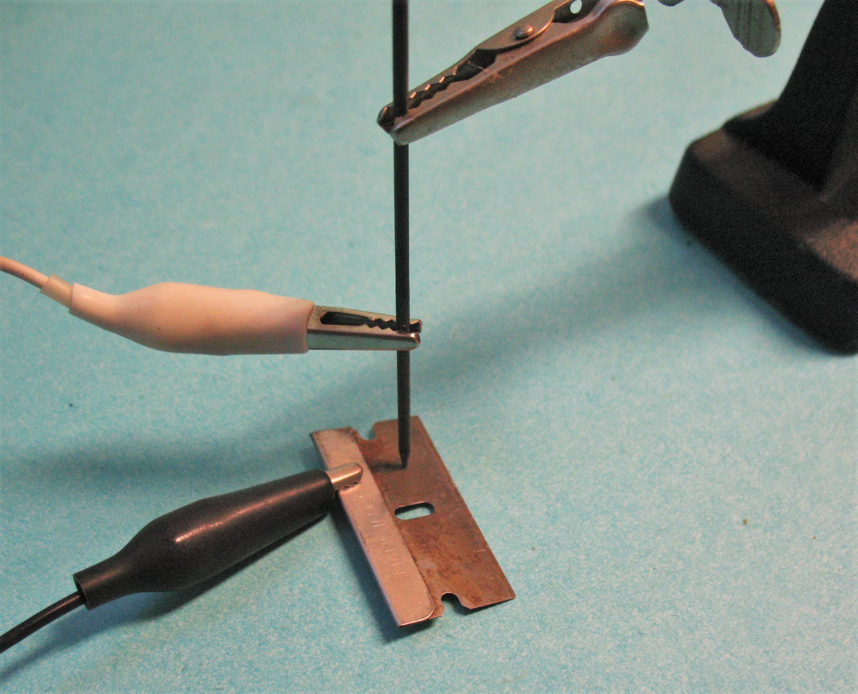
Now to try Razor Blade and pencil lead. Mechanical stability is important.
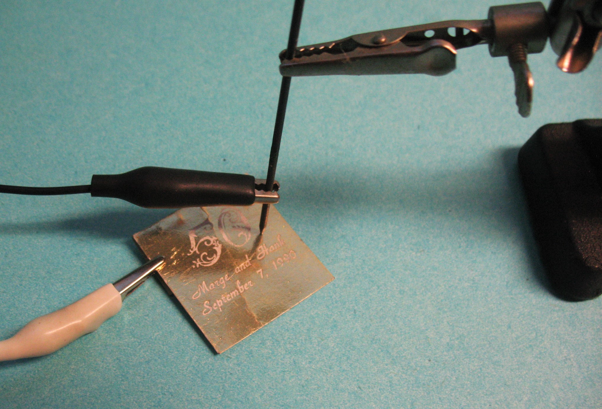
Pencil lead and Match Book cover.
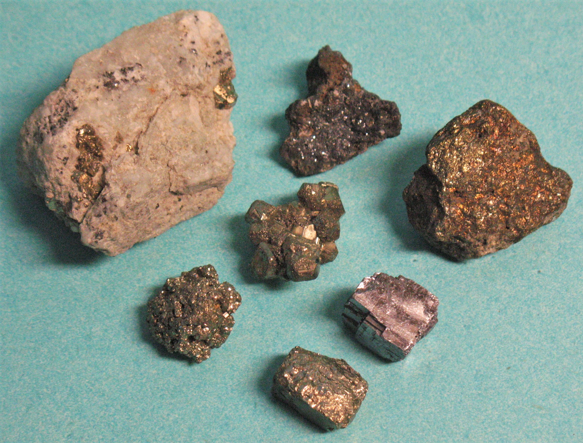
Minerals from your rock collection. Iron Pyrite and Galina. To be used with
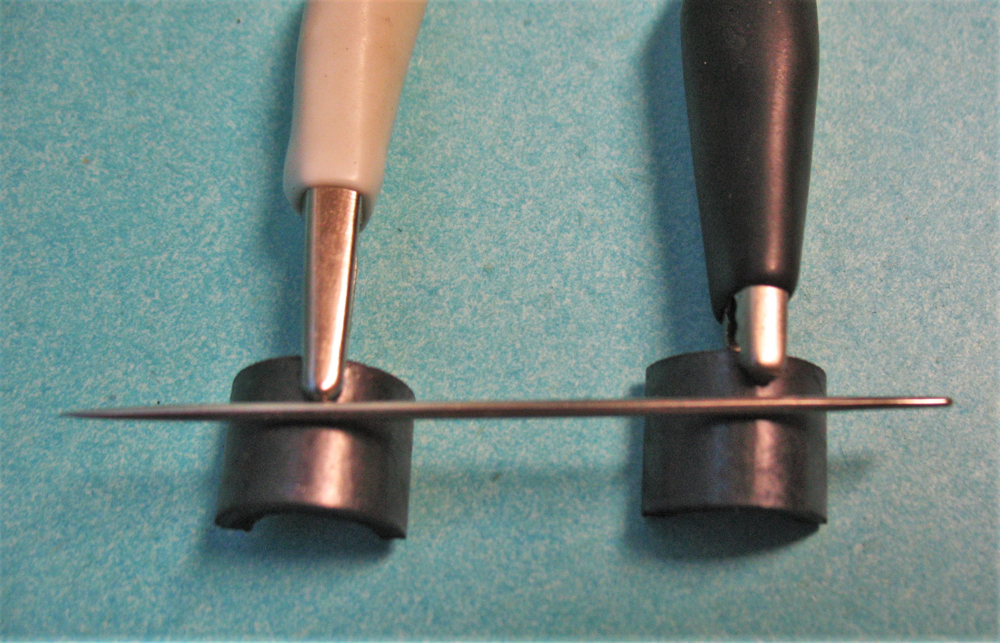
Cat's Whisker made from Phosphor Bronze or German Silver.
Phosphor Bronze on the Left and German Silver on the Right.
The cat's whisker should be bent to form a spring, to keep it in place
and to create the correct pressure. Remember only cut with scissors,
for square end.
Pressure changes can change voltage of detection, sometimes light
pressure is better, sometimes harder is better.
There is no end of what to try.
Now let us make our SatSoc Radio Better.
First we will add a link coil to our Inductor. Remove the coil from the
Radio. Drill two holes .200 from the end of the coil and two more .300
from the holes you just put in. Now wrapping in the same direction, fill
the space between the holes. Should be 9 to 11 turns. When done this coil
will be the primary and the big coil the secondary. We will hook the
antenna and ground to the Primary and this will give us better selectivity
and more voltage. Next scratch enamel off one spot on one wire in
the center of the coil. Solder a piece of wire to this scratched off spot.
By adding a wire with quick clip to the Cathode side of the Diode
or top of the coil, we now have a switch and a switch point. By
clipping the switch closed we will cut our Inductance in half. This will
let us tune the middle and high end of the band better.
Finished Upgraded SatSoc Radio
Link Close Up
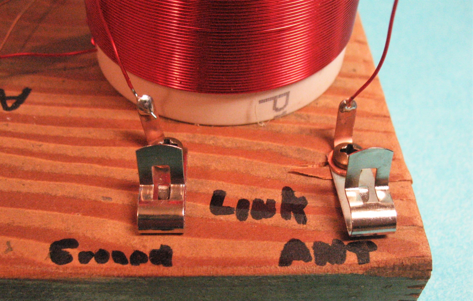
Added another set of Fahnstock's for Antenna and Ground
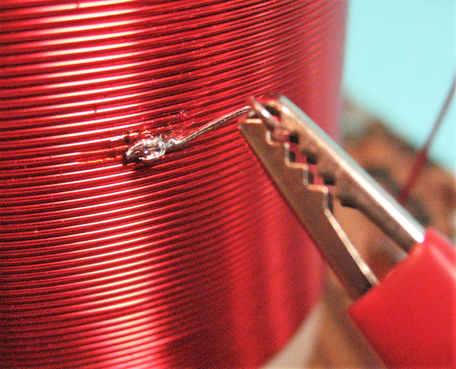
Close, the center tap, this may help some with different grounds and
Antenna systems. Day time Night time differences as well. Use to have
better reception on the high end of the band.
OK, so now that we have done some testing and upgraded the radio,
what now?
This was meant to be an introduction on building a radio from scratch.
The testing of detectors is something that is fun and interesting. Solid
state devices all have some active legs that could be used and transistors
as well. Some work, some do not.
We could build this radio hundreds of different ways. We could use
manufactured parts. New Parts or Old Parts work. We could build our
own amplifiers, front end or audio. We could substitute our detector with
an active device. We could build a one transistor Regen and get millions of
times amplification and greater selectivity. We could build it for Long Waves
Listen to MCW beacons or Build it for Short Wave and listen to Foreign Broadcast.
We could build simple Transmitter and Matched Regen and work Thousands
of miles.
So, now we know that the parts really are few, the schematics are simple.
Every step of the way in the development of Radio, Ham Radio Operators
were at the forefront. Yes it was a long time ago, and true we were not there.
But if we find it out for ourselves, standing on their shoulders, that will bring
us to today with a knowledge of yesterday and a real foundation for tomorrow.
This radio was crude, not pretty but somewhat functional.
Color, and Special Parts Make them Wondrous.
Crystal Sets
I built these, and many, many more.
WA6OTP